sheet metal drawing solidworks
In a part generated with the Sheet Metal Tools your Bend Lines are stored in the Flat-Pattern feature. Where to find Bend Lines.

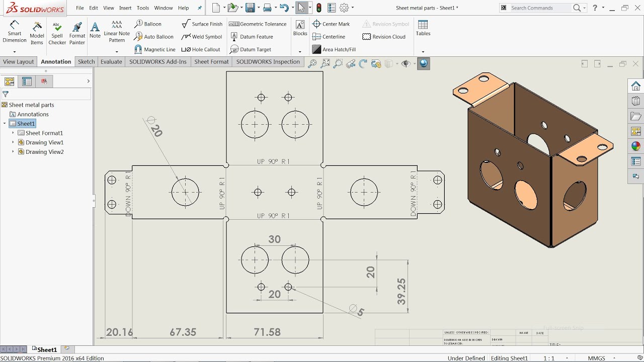
Pin By Ibrahim Unsal On Technische Tekeningen Sheet Metal Drawing Drawing Sheet Sheet Metal
In the FeatureManager design tree right-click a drawing sheet and click Properties.

. It is of circular shape so I used the hem tool but creating edge flanges on the ends does not provide the required design either. While some people may say the answer is simple there are several ways to get the Bend Lines to show or not show in your drawing. Drawings of Sheet Metal Parts - 2020 - SOLIDWORKS Help Drawings of Sheet Metal Parts When you create a drawing of your sheet metal part a flat pattern is automatically created.
Step 3 Click on the top plane and then create a new sketch. You can create dxf files of sheet metal flat patterns without creating a drawing. Drawings of Sheet Metal Parts - 2022 - SOLIDWORKS Help Drawings of Sheet Metal Parts When you create a drawing of your sheet metal part a flat pattern is automatically created.
RenderManagers 2D and 3D Sketch tools Sketch entities 3D Feature tools Motion Study Sheet Metal. This question has a validated answer. SolidWorks Sheet Metal Drawing Tutorial Bend Line Flat Pattern Unfolded Bend Table Punch Table.
To show the flat pattern. When the Flat-Pattern drawing view of a SOLIDWORKS sheet metal part displays the part in the bent configuration this often indicates an issue with the suppression state of the Flat-Pattern feature in the part file. With sheet metal designs when you have more than one body SOLIDWORKS will create separate flat patterns and cut lists on the Feature Manager Design Tree.
Step 5 Click on the Sheet Metal tab select Base FlangeTab and give 1 mm to the sheet metal parameters. Drawings of Sheet Metal Parts - 2019 - SOLIDWORKS Help Drawings of Sheet Metal Parts When you create a drawing of your sheet metal part a flat pattern is automatically created. When designing sheet metal parts the order preference for use of feature tools are as follows.
Sketch a 600 inch square rectangle that is centered on the UCS origin. February 04 2015 1803. Orient your sketch to an Isometric view.
When using the Insert Bends or Convert to Sheet Metal features apply the features as early. You can save your file at this point. In the Sheet Properties dialog box on the Sheet Properties tab click Select Sheets to Modify.
Sheet Metal Drawings - Long Rebuild Time. Click Make Drawing from PartAssembly Standard toolbar and click OK to open the drawing sheet. Click Make Drawing from PartAssembly Standard toolbar and click OK to open the drawing sheet.
Drawings of sheet metal parts can also contain views of the bent sheet metal part. Start a new inch part right click on any toolbar and check the Sheet Metal tool for the Sheetmetal toolbar to be available. With sheet metal designs when you have more than one body SOLIDWORKS will create separate flat patterns and cut lists on the FeatureManager Design Tree.
From the View Palette drag the Flat pattern to the drawing sheet. The picture below shows the Reference Configuration for the drawing view selected is DefaultSM-FLAT-PATTERN. How To Create A Jog Feature.
To create a drawing of a flat pattern. Open the sheet metal part for which you want to add a drawing. Engineering Design with SOLIDWORKS 2019 Drawing and Detailing with SolidWorks 2014 is written to educate and assist students designers engineers and professionals in the drawing and detailing tools of SolidWorks.
To change the sheet format for multiple sheets at the same time. But when it comes time to creating a 2D drawing if you have a multibody sheet metal part you will not see a flat pattern view by default when adding a model view onto the drawing. SolidWorks for Sheetmetal 1.
This tutorial show how to create production drawing for. When cuts are made into the flat pattern of a rolled sheet metal cylinder or semi-cylinder it is not always easy to extract model dimension data in a SOLIDWORKS drawing. Apart from producing 2D drawings flat patterns will also be provided along with the services of nesting the files if need be.
It might even require some significant user input for proper documentation. Hi In previous version of SW first sheet metal feature added a new linked value called thickness in equation folder. Use the Convert to Sheet Metal feature.
Launch Solidworks and create a new part. Sketches can be of machined parts or sheet metal parts. Hey Guys I am working on a frame design and need an indent in the sheet metal.
Use the Insert Bends feature. You can create dxf files of sheet metal flat patterns without creating a drawing. If you do not have the sheet metal feature tab showing already right-click anywhere on the taskbar and a dialogue box comes up.
The drawing is mildly complex 16 pages with. Without proper design intent detailing the flat pattern positions may not work. I dont understand why this.
I have a tank weldment file that is composed of 40 bodies mostly sheet metal with a few weldment pieces and some regular bodies. Create a new Sketch on the front plane. Use sheet metal features such as base-flanges edge-flanges miter flanges etc.
Open the sheet metal part for which you want to add a drawing. Right-click inside the border of a drawings Flat Pattern view and then select Annotation Cut List Properties. The model itself behaves well my issue is with working with the drawing of this part.
Step 1 First Create a New Part. Files for manufacturing will also include DXF format for laser or waterjet. You can create dxf files of sheet metal flat patterns without creating a drawing.
In the Sheet Selection dialog box select the sheets to change. Drawings of sheet metal parts can also contain views of the bent sheet metal part. Select a format or click OK to use the default format.
SOLIDWORKS Sheet Metal Properties can be added to Drawings using a predefined annotation or selectively using standard annotation property mapping syntax. The first thing that everyone needs to know is where the Bend Lines are storedcreatesaved. Select a format or click OK to use the default format.
Step 4 Now sketch and use Smart Dimension to give a dimension to the design. You would see a page similar to the image below. The secret is the annotation MUST be attached to the Flat Pattern view.
Drawings of sheet metal parts can also contain views of the bent sheet metal part. Enable the sheet metal feature tab. I used a form tool for the indent but flattening it after the design does not flatten the indent.
Step 2 Right-click on the toolbar and activate Sheet Metal. From the View Palette drag. But when it comes time to create a 2D drawing if you have a multibody sheet metal part you will not see a flat pattern view by default when adding a model view onto the drawing.
You will get your sketches converted to 3D models followed by production of 2D drawings. So now I can design multibody sheeet metal parts but how can I link each thickness value as custom property for each sheet body - I would like to show these parameters in table in drawings.

Pin On Solidworks

Advanced Sheet Metal Exercise In Solidworks Youtube Solidworks Tutorial Sheet Metal Drawing Solidworks

Pin On Solidworks Sheet Metal

Solidworks 2013 Sheet Metal Metal Furniture Design Metal Sheet Design Sheet Metal Shop

Pin On Solidworks

Advanced Sheet Metal Exercise In Solidworks Youtube Solidworks Tutorial Sheet Metal Drawing Solidworks

Pin On Solidworks Sheet Metal
Solidworks Tutorial Sheet Metal Drawings Youtube Sheet Metal Drawing Solidworks Tutorial Solidworks

Pin On Solidworks

Using Solidworks Sheet Metal Functionality Create A B Size Drawing Sheet Metal Drawing Technical Drawing Mechanical Engineering Design

Pin On Solidworks

Pin On Solidworks Sheet Metal

Autodesk Inventor Sheet Metal Drawing Tutorial Basics Youtube Sheet Metal Drawing Autodesk Inventor Drawing Tutorial

Pin On Oktatas

Pin On Sheet Metal Drawing

Pin On Solid Draw

Solidworks Sheet Metal Exercise 129 Sketched Bend Jog Forming Tool And Vent Solidworks Tutorial Sheet Metal Drawing Technical Drawing
Solidworks Tutorial For Beginners Learn How To Design A Part 07 Youtube Solidworks Solidworks Tutorial Sheet Metal

Autodesk Inventor Sheet Metal Tutorial Basics Youtube Sheet Metal Drawing Autodesk Inventor Solidworks Tutorial